Frequently Asked Questions
Ultracapacitors
What is an ultracapacitor?
Ultracapacitors, also known as electrochemical double-layer capacitors (EDLCs), are electrochemical capacitors that possess an unusually high power and energy density when compared with traditional capacitors—typically several orders of magnitude greater than a high-capacity electrolytic capacitor. Most ultracapacitors are rated in Farads, and individual cells can typically be found in the 100F to 500F range, though they can extend higher or lower. Depending on the application needed, ultracapacitors may be used as battery replacements or enable smaller, more economical battery selection. Ultracapacitors have low equivalent series resistance (ESR), allowing them to deliver and absorb high currents. Their mechanical (rather than chemical) charge-carrier mechanisms enable their long, predictable life with a smooth performance change over time.
Ultracapacitors are not a new technology. The ultracapacitor effect was first noticed in 1957 by General Electric engineers experimenting with devices using porous carbon electrodes. It was believed that the energy was stored in the carbon pores and exhibited “exceptionally high capacitance,” although the cause was unknown at that time.
General Electric did not immediately follow up on this work, and the modern version of the devices was eventually developed by researchers at Standard Oil of Ohio in 1966, after they accidentally rediscovered the effect while working on experimental fuel cell designs. Their cell design used two layers of activated charcoal separated by a thin porous insulator, and this mechanical design remains the basis for most ultracapacitors today. They first appeared as a low-energy, long-life power backup for consumer electronic devices like VCRs.
The past decades have seen substantial advances in ultracapacitor material science, construction, and manufacturing techniques, which has made them highly desirable products, especially for mission-critical applications. In recent years, these devices have found their way into consumer electronics, industrial products, and automotive applications. Today, the best ultracapacitors are extremely high-power devices with power densities of up to 20kW/kg. Compact in size (small-cell ultracapacitors are often no bigger than the size of a postage stamp), they can store much more energy than conventional capacitors and can release that energy quickly or slowly. They have long life and are designed to last the lifetime of the end product.
How do ultracapacitors work?
Generally, capacitors are constructed with a dielectric (insulator) placed between two metal plates that serve as conductors; energy is stored when, during the charging process, electrons leave one plate and accumulate on the other, building a positive charge on one plate and a negative charge on the other as the dielectric prevents the negatively charged electrons from returning to the positively charged plate. This charge separation creates a potential between the two plates, which can be harnessed in an external circuit. The total energy accumulated in this fashion is a combination of the number of charges stored and the potential between the plates. The number of charges stored is essentially a function of the size and material properties of the plates, while the potential between the plates depends on the dielectric material used.
Ultracapacitors, by contrast, generally do not have any dielectrics but rather utilize a thin coating on the metal plates to keep the positive and negative charges in place. The porous nature of the carbon coating used in this “electric double layer” gives the plates a larger surface area, which allows for a higher number of charges to be stored on them. The carbon coating used is also much thinner than any dielectric used in a traditional capacitor, which means that the distance between the separated charges is much smaller in ultracapacitors. Combined, this very small charge separation and increased plate surface area give ultracapacitors a much higher energy density than that of traditional capacitors.
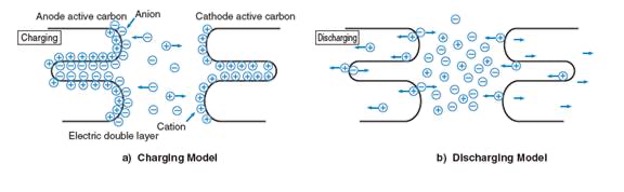
Ultracapacitor Charge Separation
To charge, ultracapacitors are submerged in an electrolyte consisting of positive and negative ions dissolved in a solvent. There are two types of electrolytes used by ultracapacitor manufacturers: One is water-soluble, and the other is non-water-soluble. The non-water-soluble electrolyte increases the withstand voltage per cell compared to that of a water-soluble electrolyte, producing a higher energy density. Tecate Group cells are made with non-water-soluble electrolytes.
How are ultracapacitors constructed?
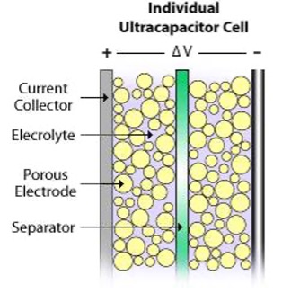
The specifics of ultracapacitor construction are dependent on the manufacturer and the intended application. The materials may also differ slightly between manufacturers or due to specific application requirements. The commonality among all ultracapacitors is that they consist of a positive electrode, a negative electrode, a separator between these two electrodes, and an electrolyte filling the porosities of the two electrodes and separators.
Internal Cell Construction
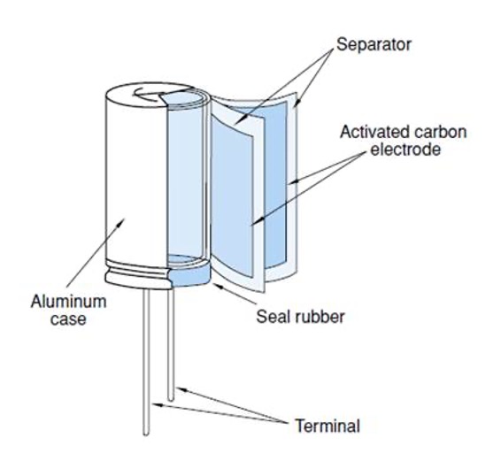
Most manufacturers have adopted a cylindrical construction method for their ultracapacitors; however, there are still products on the market that use a prismatic design. Tecate’s products use a cylindrical construction method. The cells are constructed from activated carbon particles, which are mixed with a binder and then deposited on aluminum foil. In this method, as shown in the following figure, the electrodes are wound into a jellyroll configuration very similar to an aluminum electrolytic capacitor. The electrodes have foil extensions that are then welded to the terminals to enable a current path to the outside of the capacitor.
External Cell Construction
What is equivalent series resistance (ESR)?
Ultracapacitors experience some level of internal resistance, referred to as “equivalent series resistance (ESR),” which occurs when the materials used in the ultracapacitor resist the passage of the charges from one plate to another. The amount of ESR varies depending on the particular characteristics (materials used, quality, etc.) of the ultracapacitor.
ESR (referred to as Rs in the diagram below) is the main contributor to power loss during ultracapacitor charging and discharging. The other contributing factors are parallel resistance (Rp), capacitance (C), and the series inductor (L).
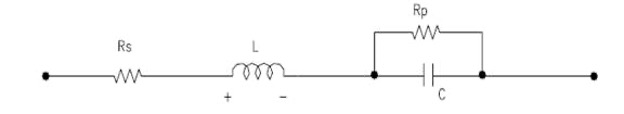
First-Order-Equivalent Circuit
Since Rp is always much larger than Rs, it can be ignored. Also, because of the porous material used on the electrodes of ultracapacitors, they exhibit non-ideal behavior, which causes the capacitance and resistance to be distributed such that the electrical response mimics transmission line behavior. Therefore, it is necessary to use a more general circuit, as shown in the figure below, to represent the real electrical response and ESR effect.
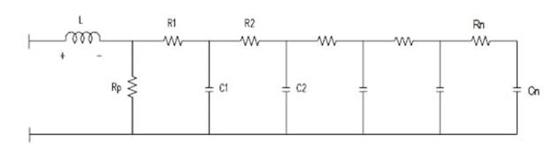
Ladder Network
What are ultracapacitor advantages and limitations?
Ultracapacitors have several distinct advantages, the first of which is their high energy storage. Ultracapacitors possess energy density that is several times higher than that of traditional capacitors. Compared with batteries, they also possess a low internal resistance (ESR), furthering their high power-density capabilities. Ultracapacitors are also capable of performing at low temperatures. Tecate Group’s ultracapacitors, with their use of patented technology, are capable of delivering energy down to -40°C with minimal effect on efficiency. And finally, ultracapacitors have very fast charge and discharge rates. Since they achieve charging and discharging through the absorption and release of ions, high current charging and discharging is possible without any damage to the parts.
Ultracapacitors do have a few limitations. They have low per-cell voltage, typically around 2.7V, which means that any higher-voltage applications require the cells to be connected in series. Also, because of their time constant, ultracapacitors are not suitable for use in AC or high-frequency circuits.
How do ultracapacitors differ from batteries?
Portable applications and digital technology have outpaced traditional chemical battery technology. A typical symptom of insufficient battery performance is the ratio of time the appliance is in use versus the appliance recharge time. Another nuisance is when a battery has to be replaced prematurely as it will no longer hold a charge. In these situations, using batteries in conjunction with ultracapacitors can improve overall system performance and extend battery life.
One reason batteries tend to need premature replacing is that, when a burst of energy is needed for an application, the high resistance of a chemical battery can cause the battery voltage to collapse. Ultracapacitors, in contrast, have a low internal resistance that allows them to deliver such bursts of energy with no damage to the ultracapacitor. This is because, unlike batteries, which discharge at a fairly constant rate, ultracapacitors act very similarly to traditional capacitors and will drop their voltage as they discharge their stored energy. When they are used in conjunction with batteries, ultracapacitors eliminate the instantaneous energy demands placed on batteries, and this in turn extends battery run time and prevents declining charge capacity as the battery ages.
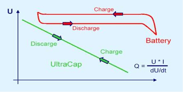
Ultracapacitor Discharge Curve
Also unlike batteries, ultracapacitors are maintenance-free and operate over a wide temperature range. They can be charged and discharged at the same rate, while batteries are limited by their slower charge rate.
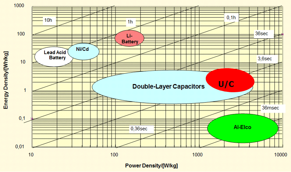
Ultracapacitor Performance vs. Battery/Conventional Capacitor Performance
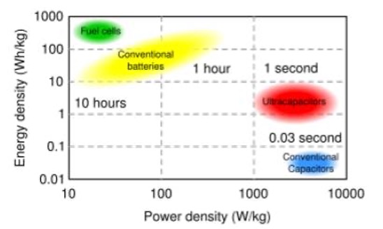
As can be seen in the chart above, ultracapacitors reside between batteries and conventional capacitors in terms of energy and power density. They are typically used in applications where batteries come up short when it comes to high power/life and conventional capacitors cannot be used because of a lack of energy. Ultracapacitors offer high power density along with adequate energy density for most short-term, high-power applications. The chart below offers a further comparison of the different technologies.
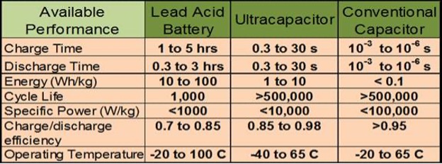
Ultracapacitors vs. Batteries and Conventional Capacitors
What is the difference between power and energy?
Although it is common to use the terms power and energy interchangeably, they are not the same. Energy is the amount of work that can be done, while power is the rate at which energy is used to do that work. In other words, power is the amount of energy used per unit of time. The two are related according to the following formula:
Power * Time = Energy
As can be seen in the chart below, ultracapacitors, traditional capacitors, and batteries fall in different places on the scale of power versus energy density. Power density refers to how quickly a device can discharge its energy, while energy density refers to how much energy a device contains. Batteries have low power density but high energy density, meaning they have a lot of energy that gets discharged slowly. Traditional capacitors, on the other hand, have high power density but low energy density, meaning they have less energy but it can be discharged more quickly. Ultracapacitors fall somewhere in the middle, with high power density and medium energy density.
Power Density vs. Energy Density
What is end-of-life and failure mode for an ultracapacitor?
In general, ultracapacitors do not have a hard end-of-life failure as do batteries. Their end of life is defined as when the capacitance and/or ESR has degraded beyond the application’s needs.
Ultracapacitor failure can be caused by placing ultracapacitors in “abuse” conditions, which include over-voltage, over-temperature, and mechanical stress conditions. Over-voltage and over-temperature conditions can result in a loss of capacitance, increased ESR, bulging, and venting. Mechanical stress conditions can result in deformation, broken leads, and increased ESR.

Failure Under Abuse Conditions
What is self-discharge and leakage current?
Over time, charged ultracapacitors without a load slowly lose their charge. “Self-discharge” is the voltage drop a charged ultracapacitor cell experiences after a set period of time without a load.
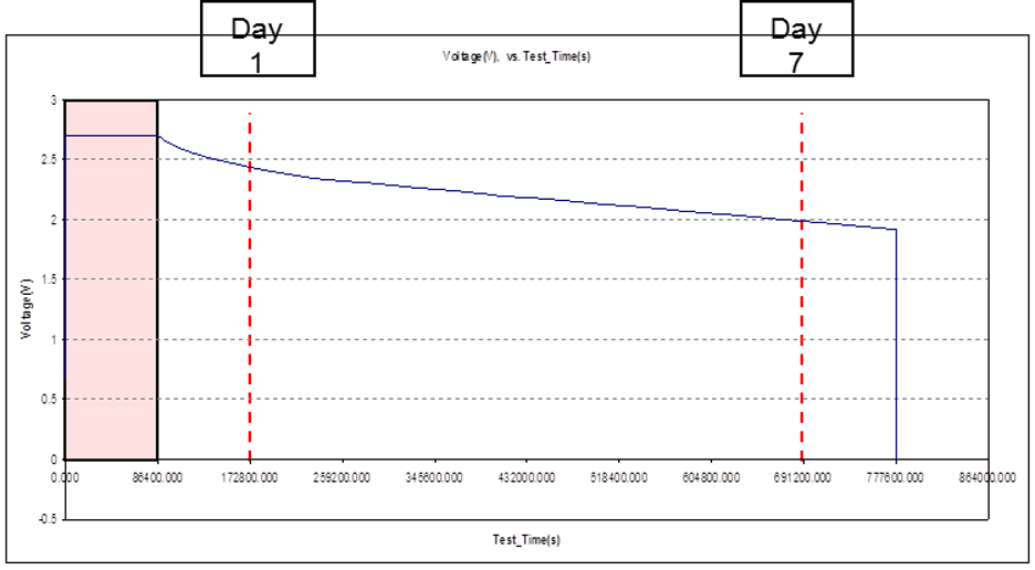
Self-Discharge
Ultracapacitors require a current to keep them charged. The leakage current is the stable parasitic current needed to hold an ultracapacitor on charge at a rated voltage. The value needed for the leakage current is voltage- and temperature-dependent.
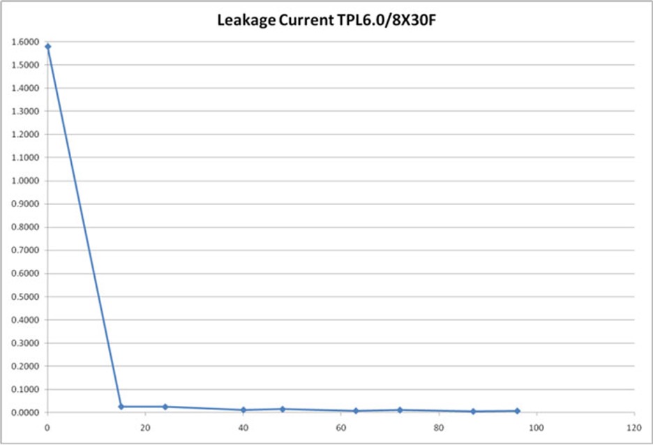
Leakage Current
Why use series/parallel combinations of ultracapacitors?
An ultracapacitor cell can only withstand low voltages. In general, if cells are operated above their rated voltages for a long period of time, their life is reduced. This is a result of the electrolyte breaking down after exposure to high voltage. The amount of damage varies based on the voltage and the amount of time the cell is exposed to the over-voltage condition. Thus, occasional spikes above rated voltage will not immediately affect an ultracapacitor, but prolonged high-voltage uses will.
The voltage rating of Tecate’s ultracapacitor cells is 2.7V or 3.0V. This higher-than-usual rating is mainly derived from the electrochemical stability of the electrolyte and electrode materials. The Tecate family of products uses an organic electrolyte. The key advantage of an organic electrolyte versus other (aqueous) electrolytes is its higher voltage stability. Yet even the higher-than-usual voltage rating of Tecate’s ultracapacitor cells is not enough to meet the required voltage of most applications.
Placing multiple ultracapacitor cells in series overcomes this limitation. This means that ultracapacitors rated for higher voltages must be made of matched, series-connected individual capacitors, much like series-connected cells in higher-voltage batteries. Depending on the required energy, there could be a need to then place multiple cells in parallel. When ultracapacitor cells are placed in series or parallel, they react very similarly to conventional capacitors. Below is a summary of how key attributes respond when multiple cells are placed in series/parallel formation:
Voltage
Series connection: When placing cells in series, the overall voltage is increased directly by the number of cells in series.
Example: 4 cells (rated at 2.7V each) connected in series will have a maximum voltage of 10.8V.
Parallel connection: Placing cells in parallel will not affect the voltage.
Example: 4 cells (rated at 2.7V each) connected in parallel will have a maximum voltage of 2.7V.
Capacitance
Series connection: When placing same-value cells in series, the system capacitance is reduced by the number of cells placed in series based on the following formula: Csys = Ccell/n.
Example: 4 cells (rated at 10F each) connected in series will have a capacitance of 2.5F.
Parallel connection: Placing same-value cells in parallel will increase the overall system capacitance directly by the number of cells placed in parallel.
Example: 4 cells (rated at 10F each) connected in parallel will have a capacitance of 40F.
ESR
Series connection: When placing same-value cells in series, the overall system ESR will increase directly by the number of cells placed in series.
Example: 4 cells (DC ESR 75 mΩ each) connected in series will have a total ESR of 300 mΩ.
Parallel connection: Placing same-value cells in parallel will decrease the overall system ESR proportionally to the number of cells placed in parallel, according to the following formula: ESRsys = ESRcell/n.
Example: 4 cells (DC ESR 75 mΩ each) connected in parallel will have a total ESR of 18.75 mΩ.
Leakage Current
Series connection: Placing same-value cells in series will not affect the leakage current.*
Example: 4 cells (each with a leakage current of 0.03mA) connected in series will have a total leakage current of 0.03mA.
Parallel connection: Placing same-value cells in parallel will increase the overall leakage current directly by the number of cells placed in parallel.*
Example: 4 cells (each with a leakage current of 0.03mA) connected in parallel will have a total leakage current of 0.12mA.
*It should be noted that this does not take into account any leakage current induced as a result of cell balancing. In the case of passive balancing, the leakage current will be dominated by the bypass resistor value.
Why do ultracapacitors require balancing, and what are the balancing methods?
For most applications, a single ultracapacitor cell at low voltage is not very useful, so normally multiple ultracapacitor cells are connected in series to achieve the required system voltage. Since ultracapacitor cells have a tolerance difference in capacitance and leakage current, there will always be an imbalance in the cell voltages of an ultracapacitor series string. It is important to ensure that the individual voltage of any single ultracapacitor cell does not exceed its maximum recommended working voltage, as this could result in reduced life.
This voltage imbalance is immediately dominated by the capacitance difference between the ultracapacitor cells because a cell with a lower capacitance will charge to a higher voltage in a series string than the other cells with higher capacitance. For example, if two 2.7V ultracapacitor cells, each rated at 10F, are connected in series, with one cell at +20% of nominal capacitance and the other at -10%, then the highest possible voltage for each ultracapacitor cell can be calculated as follows:
Vcap1=Vsupply x (Ccap1/(Ccap1 + Ccap2))
Assuming Vsupply=5.4V
Vcap1=5.4 x (12/(12+9))
Vcap1=3.08V
A voltage of 3.08V is too high for a single ultracapacitor cell rated at 2.7V; thus, series-connected ultracapacitor cells require a proper cell-balancing scheme to ensure that no cell sees a higher-than-rated voltage condition.
When an ultracapacitor series stack is on charge for a period of time, leakage current may also affect the voltage distribution among the cells. In this case, a cell with a higher leakage current will discharge to a lower voltage, distributing the remaining voltage among the other cells and resulting in an over-voltage condition. Proper cell balancing can eliminate this imbalance.
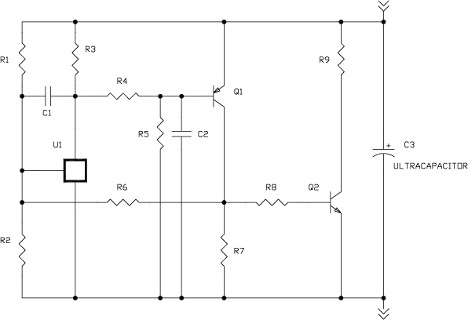
There are two balancing schemes to eliminate uneven voltage distribution and ensure a properly balanced ultracapacitor module: passive balancing and active balancing.
Passive Balancing (Figure 1): One technique to compensate for variations in individual cells is to place a same-valued bypass resistor in parallel with each cell, sized to dominate the total cell leakage current. This effectively reduces the variation in equivalent parallel resistance between the cells, which eliminates differences in the leakage current. For example, if the cells have an average leakage current of 10uA +/- 3uA, using a 1% resistor that will bypass 100uA in parallel to each cell will change the average leakage current to 110uA +/- 4uA and decrease the variation in leakage current from 30% to 3.6%. Having the same-value resistor in parallel with all cells also allows the cells with higher voltages to discharge through the parallel resistor at a higher rate than the cells with lower voltages. Together, these effects help to distribute the total voltage evenly across the entire series of ultracapacitor cells.

Passive voltage balancing results in a high self-discharge, so is only recommended for applications that have a constant power supply connected to offset the additional load current of the balancing resistors. If this method is appropriate, the balancing resistors should be selected to give an additional current flow of at least 10 times the worst-case cell leakage current. Higher ratios can be used to balance the cells faster, if the series can tolerate the increased current load. Once the system is balanced, the time it takes to keep the system in balance is less of an issue unless there is a high frequency duty cycle.
Active Balancing (Figure 2): An Active voltage balancing circuit works by forcing the voltage at the nodes of series-connected cells to stay below a fixed reference voltage. Active circuits typically draw much lower levels of current in a steady state and only require larger currents when the cell voltages go out of balance. These characteristics make active voltage-balancing circuits ideal for applications that may not have a power supply connected continually to offset the higher self-discharge of a Passive balance scheme. Active balancing circuits are more complex than Passive, and most applications with a constant power supply will select Passive Balancing. If self-discharge is a concern, and the power supply is not always available, then an Active Balancing circuit is normally selected.
How does temperature affect ultracapacitors?
One of the main advantages of ultracapacitors is their wide temperature range. The effects extreme temperatures have on ultracapacitor cells depends on whether the temperature is extremely high or extremely low. Operating at extremely high temperatures will reduce the life of the cells, while operating at extremely low temperatures will increase the internal resistance of the cells.

Effect of Extremely Low Temperatures on Ultracapacitors
What are the steps to perform a constant current discharge test?
A constant current discharge test can be useful for customer evaluation of an ultracapacitor module prior to application testing. Please note that, for safety reasons, Tecate stores all of its ultracapacitor cells and modules in a discharged state and recommends that customers completely discharge any ultracapacitors that will not be immediately installed into equipment.
Required Equipment
- Ultracapacitor module
- Bidirectional power supply (supply/load) or separate power supply and programmable load (capable of providing a constant current)
- Voltage vs. time measurement/recording device (digital scope or other data acquisition)
- Current vs. time measurement/recording device (optional if the power supply and load settings are trustworthy)
- Before testing, connect the data-acquisition equipment to the device terminals and set recording speeds as fast as reasonably possible (<<100msec preferred). The faster the recording speeds, the more accurate the calculations will be.
Setup
- Set the power supply to the appropriate voltage and current limits, and turn the supply output off. The current limit can be anything at or less than the maximum rated current for the lowest-rated cell in the series. The voltage limit is the maximum cell voltage times the number of cells in the series. Each cell’s voltage should be limited to the maximum rated voltage for the lowest-rated cell in the series.
- Having preset the current and voltage limits, connect the ultracapacitor module to the power supply. Cooling air may be required to keep the module within operating temperature limits, depending on the test current and duration.
- Connect the voltage and current measuring/recording devices.
Charge
- With the power supply preset and the ultracapacitor module connected, turn the supply output on.
- Charge the module at the appropriate current to the appropriate voltage.
Discharge
Note: If you are using a separate programmable load instead of an integrated bidirectional power supply, disconnect the charging power supply prior to discharging. Do not simply turn it off or change its set points, as many supplies will sink current when not regulating.
- Set the load to the appropriate constant current, and discharge the module to 0.1V, or as low as the load can be controlled. Depending on the equipment, some modules can be discharged to 0.1V and others to half of their initial voltage. Capacitance values will be slightly higher when the modules are discharged to half of their initial voltage rather than 0.1V.
- Immediately remove the load once the minimum voltage is reached, allowing the module’s voltage to bounce back.
- Measure the following parameters:
- Vw (inital working voltage)
- Vmin (minimum voltage under load)
- Id (discharge current)
- Vf (voltage 5 seconds after removal of load)
- td (time to discharge from initial voltage to minimum voltage)
- Calculate the capacitance according to the following formula: Capacitance = (Id * td)/(Vw – Vf) (This change in voltage (Vw – Vf) is used because it eliminates the voltage drop due to the equivalent series resistance (ESR).)
- Calculate the ESR according to the following formula: ESR = (Vf – Vmin)/Id (An LCR meter or bridge can be used to measure ESR at higher frequencies. The ESR at frequencies up to 100Hz will typically be 50-60% of the DC ESR. The capacitance will be much lower, due to the structure of the electrode.)
Representative Measurement Points for Constant Current Test
Safety Considerations
As with all electrical testing, the investigator should take appropriate precautions in the design and execution of the test. Proper precautions for the voltage should be observed. Any interconnections should be sized for the maximum anticipated current and insulated for the appropriate voltage. If repeated testing will be performed, cooling air may be required to keep the test module within its operating temperature range.
What is the best way to size an ultracapacitor for an application?
The system variables needed are used to calculate the size and number of ultracapacitor cells appropriate for any application. In order to get the most accurate assessment of what is necessary, the following parameters need to be defined:
- Maximum charged voltage of the ultracapacitor cell or module (Vmax)
- Working voltage of the ultracapacitor cell or module (Vw)
- Minimum voltage of the ultracapacitor cell or module (Vmin)
- Required current (in amps) to discharge the ultracapacitor cell or module (I)
- Duration (in seconds) of discharge from Vw to Vmin (td)
- Total capacitance of the ultracapacitor cell or module (C)
- Equivalent series resistance of the ultracapacitor cell or module (ESR)
These values can be used in some simple exercises to determine the size and number of ultracapacitor cells required for the application. The size and number of cells required depends upon the total ultracapacitor discharge-cycle voltage drop. During the discharge cycle of an ultracapacitor, there are two voltage-drop parameters to consider: the voltage drop due to equivalent series resistance (ESR) and the voltage drop due to capacitance.
Discharge Curve
As can be seen above, during a discharge cycle the initial voltage drop is due to the ultracapacitor’s ESR. The amount of the drop is a function of the ESR and discharge current as indicated by the following equation: dVESR= I * ESR
After the initial voltage drop due to ESR, the capacitor will discharge according to its capacitance and discharge current, as indicated by the following equation: dVcap= I * td/C
By placing these two equations together, the total voltage drop can be calculated per the following equation: dVTotal = I * td/C + I * ESR
The total voltage drop indicates the number and size of the ultracapacitor cells required to meet the demands of the application. Please note that allowing a larger drop in voltage will reduce the necessary capacitance. Typically, by allowing the ultracapacitor cell or module to drop to half of the Vw value, 75% of the ultracapacitor’s energy will be discharged.
What are the soldering and handling requirements for ultracapacitors?
Tecate Group carries a variety of different ultracapacitor cells. Most of these products are designed to be mounted to PC boards by way of soldering, and all of them are RoHS-compliant and thus have lead-free preparations that require adjustments in the processes used to interconnect them with their substrates.
Please note that the process and parameters described here were developed on specific equipment and apply most fully to that equipment. It is very likely that alternative pieces of equipment will require fine-tuning of those parameters to achieve optimal results.
General Precautions
There is a risk of the ultracapacitor cells deteriorating due to excessive heat exposure during soldering, and there may also be a buildup of internal pressure. Depending on the type and size of the board, overheating the ultracapacitor cells may also cause the safety vent to burst. These outcomes will greatly shorten the life of the cells and may cause leaking problems.
Be sure not to dip the entirety of the ultracapacitor cell bodies into melted solder and to only flux the leads of the cells. Ensure that there is no direct contact between the sleeves of the ultracapacitor cells and the PC board or any other component as excessive heat during soldering may cause sleeves to shrink or crack. Similarly, do not touch the sleeves with the soldering rod, as that can cause them to melt or crack.
Hand Soldering
In order to solder ultracapacitor cells by hand, good soldering practices must be used. The solderer should have experience with hand soldering of electronic components and understand fundamental soldering processes. In general, lead-free soldering by hand requires higher heat and more active fluxes than solder containing lead as a constituent. Therefore, new thermal profiles must be adopted and new cleaning agents should be used.
The recommended temperature of the soldering rod tip is no more than 350°C. The soldering duration should be shorter than 3 seconds. Minimize the time that the soldering iron is in direct contact with the terminals of the ultracapacitor cells, as excessive heating of the leads may result in higher ESR.
Wave Soldering
In order to wave solder components, special attention must be paid to the dwell time and total time at temperature, since ultracapacitors are temperature-sensitive components. Preheat the board from the bottom side only, bringing the top of the board to 100°C, maximum, immediately before soldering. The preheat time will depend upon the heating efficiency, but use a maximum preheating time of 60 seconds.
The recommended conveyor speed is 2.8cm per second, and the soldering duration time should be shorter than 2.5 seconds. Minimize the time that the soldering iron is in direct contact with the terminals of the ultracapacitor, as excessive heating of the leads may result in higher ESR.
Due to the relatively high thermal masses of the components, and especially if the total number or density of the components is high, the use of a standard thermo-profiling device is strongly recommended to avoid excessively high temperatures.
Automated Soldering
Soldering may be automated with a hot-bar soldering jig, with soldering irons mounted on an automated raise-lower device with time and pressure controls. It is also possible to mount cells using conductive adhesive, ultrasonic welding, or laser welding.
Washing
Do not use solvent cleaners, as these may damage the device packaging; improper solvents include acetone, benzene, isopropyl alcohol, and halogenated solvents. Instead, use only aqueous cleaning solutions based on deionized water.
Washing should take place at elevated temperatures not exceeding 70°C. Spray pressures should not exceed 50psi.
Drying
Post-wash drying should be kept to the minimum necessary duration, at temperatures not exceeding 80°C. Rapid airflow around the modules during drying will assist in the removal of moisture trapped in the packages.
Capacitors
What is a ceramic capacitor?
Ceramic capacitors have ceramic as the dielectric (insulating) material used between the plates of the capacitors in their manufacturing process. Ceramic is used for its ability to permit electrostatic attraction and repulsion to take place across it. Ceramic is an excellent dielectric material because it is a poor conductor of electricity while being an effective supporter of electrostatic fields.
Ceramic capacitors are manufactured using a tape-casting process wherein thin layers of conductive electrodes are separated by a dielectric layer, and a kind of multilayer “sandwich” is formed to create a ceramic capacitor with a very large surface area in a very compact size. Recently, the combination of nickel electrodes and the ability to cast very thin layers has allowed the capacitance range of ceramic capacitors to exceed more than 100μF in an 1812 package, using X5R dielectric material. With the ability to stack hundreds of layers to form a single high-density, high-capacitance multilayer ceramic capacitor, new application opportunities—previously the sole domain of tantalum capacitors—are now available for ceramic capacitors.
Prior to the use of nickel electrode systems, palladium (Pd) and silver (Ag) were the most common electrode materials. This precious metal became cost prohibitive when making high-capacitance, high-layer-count ceramic capacitors. Palladium and silver are still widely used for ceramic capacitors with lower capacitance values.
There are now a number of ceramic materials and compositions that are used in ceramic capacitors, including ceramic COG (NPO), ceramic X5R, and ceramic Y5V. COG (NPO) is a high-Q, low-K, temperature-compensating type of dielectric with stable electrical properties across varying voltage, frequency, and time. It is suitable for circuits that require low loss, as well as in timing and tuning applications. NPO ceramic capacitors offer the best capacitance precision.
The X5R dielectric has moderate K values and stable temperature. It shows moderate change in electrical properties across changing temperature, voltage, and frequency. It is suitable for bypassing, coupling, and frequency-discrimination circuit applications. X5R ceramic capacitors show no more than a 15% capacitance deviation over the temperature range -55°C to +85°C.
The Y5V dielectric is a Class III dielectric that exhibits a maximum capacitance change of +22%, -82% over an operating temperature range of +30°C to +85°C.
Disc ceramic capacitors combine a solid body of high-temperature, ceramic-resistive material with bonded metal contacts. Multilayer disc ceramic capacitors are constructed using an alternating stack of conductors and insulators, connected on both sides by a common termination. The standard termination material for ceramic capacitors is nickel barrier with a 100% tin coating to comply with the latest RoHS standards. These ceramic capacitors are available in radial-leaded, conformal-coated packages or the more popular surface-mount configuration that is well suited for high-speed pick and place mounting.
What is a film capacitor?
Film capacitors, as a category, include any capacitor type made from plastic: polyester, polypropylene, polystyrene, and so on. There are at least two types of film capacitors: Film-foil capacitors are constructed of layers of plastic film dielectric wound alternately with metal foil electrodes. Metallized film capacitors are constructed of film dielectrics on which the metal electrodes have been previously vapor-deposited. The layers are wound into a convoluted roll, with electrodes extending beyond the dielectric films.
Film capacitors are designed using a number of different dielectrics (the insulating material between the plates of the capacitor). Dielectric materials are chosen for their ability to permit electrostatic attraction and repulsion to take place across the film. The dielectric materials ensure that any energy required to establish an electric field is recoverable, in whole or in part, as electric energy. In other words, good dielectric material is a poor conductor of electricity while being an effective supporter of electrostatic fields. Common dielectrics used in film capacitors include polyester, polycarbonate, polypropylene, and polystyrene.
Polyester film capacitors offer a high dielectric constant and high dielectric strength with volumetric efficiency. Metallized polyester film has excellent self-healing properties, and typical applications for such capacitors include bypassing and coupling.
Polypropylene provides very low losses, low dielectric absorption, and high dielectric strength. In addition, polypropylene film capacitors offer very high insulation resistance and a negative temperature coefficient. Typical applications include stable oscillators and filters, sample and hold circuits, and pulse-handle circuits. Tecate’s film capacitors are primarily used for circuit bypass, blocking, and filtering.
What is a conductive polymer capacitor?
Conductive polymer capacitors have unique characteristics achieved by using electroconductive polymer as electrode material. In a solid-state capacitor comprising a positive and a negative electrode, a dielectric medium, and a solid electrolyte, the solid electrolyte contains an electroconductive polymer as an essential constituent. Electroconductive polymer capacitors do not use liquid electrolyte, so they will not dry out, leak, or suffer gas buildup and burst. The circuit-level benefits of this type of capacitor include low equivalent series resistance (ESR), high ripple current, longer life, and high temperature capability.
What is a tantalum capacitor?
Tantalum capacitors are used in electronic devices including portable telephones, pagers, personal computers, and automotive electronics. When selecting between available tantalum capacitors, there are a number of key specifications to keep in mind, including capacitance value, capacitance tolerance, dissipation factor, leakage current, board interface requirements, and equivalent series resistance (ESR). Tecate’s tantalum capacitors are available in radial-leaded or surface mount configurations.
Capacitance is a measure of the energy storage ability of a tantalum capacitor, given as C = K A/D, where A is the area of the electrodes, D is their separation, and K is a function of the dielectric between the electrodes. The formula yields a result in farads (F), but a farad is so large that the most commonly used values are expressed in microfarads (µF = 10-6F).
The dissipation factor (DF) is the ratio between the resistive and reactive parts of the impedance of the tantalum capacitor submitted to a sinusoidal voltage of specified frequency. It is a measure of the losses in the capacitor.
Leakage current is measured as the current flowing from one conductor to an adjacent conductor through an insulating layer. The leakage current in tantalum capacitors is measured after 3 minutes at 25°C, through a 1k resistor connected in series with the capacitor, and with rated voltage applied.
ESR represents the extent to which the capacitor acts like a resistor when charging and discharging. This functions via a resistive element within the capacitor model, found in both the AC and DC domains. The lower the ESR, the higher the current-carrying ability of the tantalum capacitor.